| Allt Nytt | Kalender | Racerbanor | Arrangörer | Forum | Varvtider/Loggar |


 |
RejsaRubberTrac
 PCB = no internal cables
|
4600 besök totalt |
|
Senast ändrad av Magnus Thomé, 05 Feb 2019 16:15, ändrad totalt 9 gånger
You don't need this board! Connect the sensor daughter board/boards with just five wires and you're done.
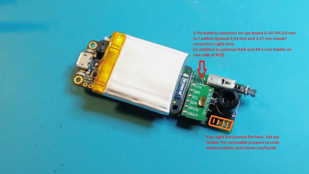
---- But... this has swiss army knife style options to pick and choose from, whatever you feel you need: - 12 volt power input. This means you can run the board directly from the car's power or other sources up to 30V. Both through hole and smd components fit. - Simple power on/off switch. Not the final solution for tough environments but you can connect cables to a tougher one here instead if you want. If no power switch is present the board defaults to be powered on thanks to the switch activating a power disable pin on the power circuit when it's present and activated. - You can sandwich mount a temp sensor daughter board OR just direct mount temp sensor as a component. - You can sandwich mount a distance sensor daughter board OR direct mount distance sensor as a component (surface mount) - Li-Ion battery holders. So you have the choice of connecting either a flat chargeable Li-Po battery to the JST connector or use a battery holder for either a Li-Ion AAA (10440) or AA (14500) size chargeable battery. Li-po connectors are either JST-PH 2.0 or 2,54 or 1,27 mm. - Three pin headers for removable jumpers for optionally coding each sensor unit to be named (Bluetooth device name) Front/Rear and Left/Right. This can alternatively be set in the software code before uploading to each sensor. - One pin heaqder for a removable jumper for optionally mirroring outside/inside of the tire for the temperature sensor. This can alternatively be set in the software code before uploading to each sensor. - All components but the distance sensor can be either through hole or surface mount. 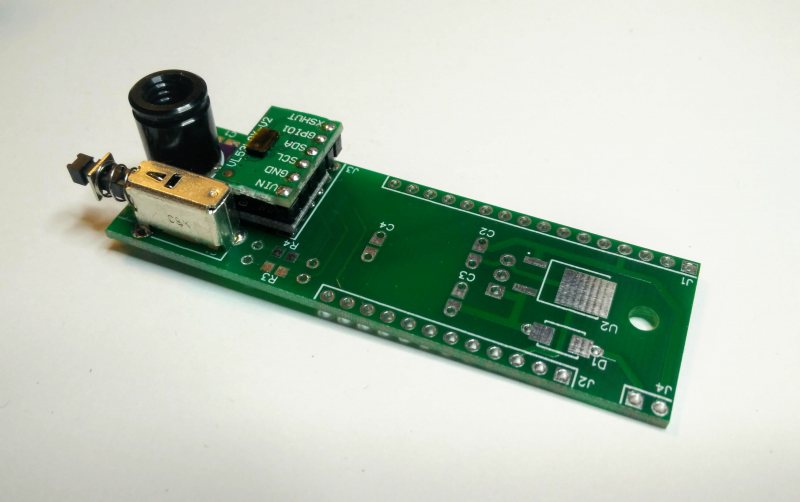
_________________  Magnus Thomé Magnus Thomé

|
||
|
Skipped that for now due to limited space. But I could definitely add that if I look and find some really small dip switches!
1. Default: Upload code to sensor as is --> each sensor gets a unique Bluetooth device name 2. Edit one value setting in the code before uploading --> the name will also include LF, RF, RL and so on (plus unique address) 3. Or upload code as is AND cut thin jumper with a knife --> the name will also include LF, RF, RL and so on (plus unique address) The code to edit to get "wheel position" in the Bluetooth name:
EDIT: Actually, the three solder jumpers (they are connected by default and you cut them with a knife) also have mounting holes and smd for pull up resistors. So if you mount smd resistors for pull ups there are already exacxt matching holes for a dip switch. But where it sits clashes with where the battery is... _________________ Magnus Thomé
|
||
|
Its a nice feature.
But you still have to select/code the sensors to the correct position in the app? If the app cant decode the letters by itself? Manual selection is probably better; if a front sensor fails and I don't have a spare, I maybe want to move a rear sensor to the front? The box is placed in a very ruff environment, cutting is better than switches? _________________ Samuel Hyving Lekbil: Chrysler PT Cruiser GT
|
||
|
Senast ändrad av Magnus Thomé, 02 Feb 2019 17:07, ändrad totalt 1 gång
Yeah, you'll be able to place any sensor in any position in the app anyway so it's really just that it's easier to remember the name, nothing else. This can for example be the name of the front left sensor in your setup: RejsaRubber6412051B. And then in compariosn RejsaRubberFL12051B is (just) slightly easier to remember where it goes. But also remember that you normally really only assign the sensors in the app once (apart from spares exactly as you mention). So it's a non issue really. The only really important part is marking the outside of each box where it is supposed to go on the car (if you remove them to recharge them every time) _________________ Magnus Thomé
|
||
|
Edited the OP:
- Three solder jumpers (knife cut trace) for optionally hardwiring each sensor unit to be named (Bluetooth device name) Front/Rear and Left/Right. This can alternatively be set in the software code before uploading to each sensor. - One solder jumper (knife cut trace) for optionally mirroring outside/inside of the tire for the temperature sensor. This can alternatively be set in the software code before uploading to each sensor. _________________ Magnus Thomé
|
||
|
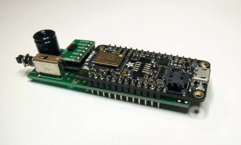
Yaaay, found a small small space in a corner where I could fit a pin header for coding wheel position with small removable jumpers. It just just clears the IR daughter board. So no trace cutting or solder jumps needed.
A, B, C for wheel position "Mirr" for mirroring tire outside/inside of temps 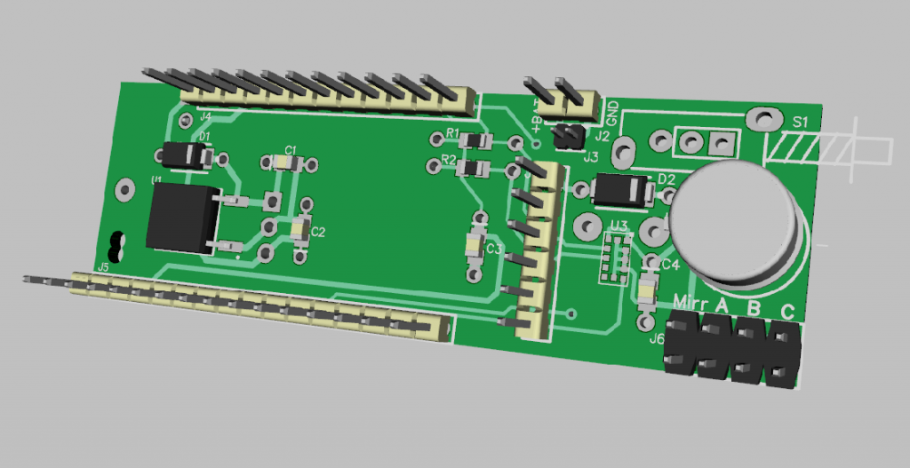
_________________ Magnus Thomé
|
||
|
RejsaRubberTrac
PCB = no internal cables
|
4600 besök totalt |


