| Allt Nytt | Kalender | Racerbanor | Arrangörer | Forum | Varvtider/Loggar |

 |
SÄLJES
 SÅLD: Ny J&S Knacksensor Kit (Universal + Miata)
|
2 besök senaste veckan (367 totalt) |
|
Senast ändrad av Carl Johansson, 04 Nov 2021 22:35, ändrad totalt 2 gånger
Ny J&S Knacksensor med sensor/lambda display för montering i instrumentpanelen.
J&S Knacksensor sänker endast tändningen på den cylinder som knackningen sker på och nästa gång kolven går upp i samma cylinder, så är tändningen redan sänkt. Knacksensorn är universal och alla kablar, slangar etc ingår. Det ingår även en extra kabelhärva för Mazda MX-5 Miata NA och NB (Första modellerna) Säljes för en liten bråkdel av inköpspriset! Pris: 950 kr eller bud! J&S Safeguard Installation A J&S safeguard is a timing controller that I know of that retards individual cylinder timing to allow maximum timing per cylinder. At $600 for the control box and display its not cheap. Using a single knock sensor, the system detects the onset of detonation and retards the timing on a per cylinder basis. A mode switch lets you select a maximum of either ten degrees or twenty degrees of knock retard. In the ten degree range, the unit retards one, two, or three degrees per ping. Double that for the twenty degree range. The system is always trying to re-advance to stock timing. In the ten degree mode, it re-advances at the rate of one degree every twenty revolutions. J&S Wiring Diagram Installation Directions The unit must be installed in the passenger compartment Cut the thre Ignitor drive wires at a convenient point. Connect the Safeguard to the cut ends as shown using 6 conductor cable supplied in the kit. Connect the J&S RED wire to a switched power source. Note that the 12V must be present during cranking and running. Connect the J&S BLACK wire to chassis ground. Connect the "CLEAR" wire of the J&S knock sensor cable to the factory knock signal wire. Tap the signal near the ECU. Avoid cutting through the shield on the factory Knock Sensor cable. At a convinient point, cut the 1/8" nylon tubing that feed the vaccum/boost gauge. Install the supplied brass compression tee fitting in line. Connect one end of the supplied vaccum hose to the brass tee, and route the hose to the back end of the J&S unit. For now cap the hose leaving the brass fitting at the back of the unit open. Initial Test At the key On, the unit performs a self check. The status LED will flash 10 times over a 2 second period. If you have an optional Safeguard Bargraph display will count up and back down. Turn the ignition key off and back on again, and insure that the Status LED flashes. Note that is the J&S RED wire is connected to the battery (not ignition), the self test will not repeat (and the battery will get discharged). The self test is bypassed when the engine is cranked over. After double checking you work, crank the engine. During cranking, the Status LED on the front panel should pulse with each spark event. If the pulse is irregular stop and check your work again. The pulses should be very evenly spaced. Above 980 RPM, the Status LED goes out, and above 1750 RPM, the function of the LED changes to indicate Knock retard. The brightness will vary in proportion to the amount of Knock retard. Knock Retard The unit ignores the knock sensor until the following conditions are met: Engine Exceeds 1750 RPM Vacuum drops below 5 inches To test the knock retard function, temporarilly Set mode switches 1& 2 on teh front panel up. This sets the unit to 20Deg knock retard range, and retard all cylinders, making it easier to tell that the unit is retarding. Leave the the vaccum/pressure port on the back of the unit open. This forces the onboard MAP sensor to 0 psi. Run the engine to 2000 RPM Have an assistant tap rapidily on or near the knock sensor You should hear the engine slow down as it retards. Verify this with a timing light. Check that the Status LED glows. Boost Retard If you wish to preset and verify the amount of boost retard, temporarily connect a MityVac or equivalent hand pump to the brass fittting on the back of the unit. Set the Boost Retard "Start" Knob fully CCW, to insure the boost retard will start at 0 psi. Set the "Rate" knob for the desired amount of retard per psi. Fully CCW is 0, mid range is 1 Deg per psi, fully CW is 2 Deg per psi. Proportional amounts in between. Start the engine. Apply the desired amount of pressure to the unit. With a timing light, verify the amount of boost retard. Tune the amount, using the "Rate" knob. Use the Boost Retard "Start" knob to change at what psi boost retard begins. If set to mid-range, the boost retard will not begin until 5 psi. Fully CW, and boost retard will not start until 10 psi. Note that the maximum amount of boost retard is 20 Deg, and is in addition to any amount of knock retard. The onboard MAP sensor reads up to 15 psi. RPM Retard To offset the agressive factory timing curve at high RPM, the unit has a RPM based tetard curve. Mode switches 3 and 4 allow you to select 0,2,4 or 6 degrees or RPM retard. See table below: S3 S4 Retard 1 1 = 6 Deg (note 1 = UP) 1 0 = 4 Deg 0 1 = 2 Deg 0 0 = 0 Deg Assuming the boost exceeeds 4 psi, the retard begins at 5250 RPM, and increases linearly with RPM, and is all in by 6250 RPM If boost is less than 2 psi, there is no RPM retard. Between 2psi and 4psi, proportional amounts Switched Retard An additional amount of retard is added when the "Aux" pin (pin 2 of the harness connector) is switched to 12V. Mode switch S5 UP adds 4 Deg, DOWN adds only 2 Deg. The "Aux" wire may be connected to a nitrous solenoid, or wire it to a "LOW OCTANE" switch. Sensitivity Adjust The sensitivity must be set on a road test. For Safety take along an assitant. Piston engines can be noisy a low loads, due to piston slap. For this reason, the unit ignores knock sensor until vaccum drops below 5 inches. Bring the vehicle to freeway cruising speed. Temporarily disconnect the vaccum hose from the rear of the unit, plug the hose Start with the Sensitivity knob fully CCW, and turn it CW slowly, until the unit just starts to detect engine noise, then back it off slightly. The engine should not be in boost at this time. Reconnect the vaccum/boost hose. Tuning Maximum power will be achieved at the threshold of knock. The Status LED can be used as a tuning aid. Adjust the Boost Retard "Start" and "Rate" knobs for minimum knock retard activity. At high RPM, use mode switches S3 and S4 to select an additional amount of RPM based retard. The status LED can be used in assit in tuning the fuel curve. Check the A/F ratio when you see knock retard activity. If you have the optional remote status LED Kit, remove the front panel, pull the exisitng LED from its socket, and install the two pin mini plug into the socket. Make sure that the pin with the wire is on the left. Mount the LED where it is easily seen, It uses a lens to focus the light, so it should be viewed head on. Ground the black wire of the LED at a convenient place on the chassis. Optional Knock Gauge Install Dualmonitor.jpg 2001Black.jpg RetardDisplay.jpg The guage on the left is a Dual Knock and Air/Fuel Ratio gauge. The other gauges are knock only. Two cables are supplied with the Guage. The cable with the two 3.5 mm plugs connects the Retard display to the SafeGuard, while the 2.5 mm shielded cable connects the O2 Display to the O2 Wires. Connect the Clear wire of the shielded cable to O2 signal, the Black wire to the O2 reference or Ground, and the bare shield wire to chassis ground. For 1 wire sensors connect both Black and Shield wires to ECU ground. Bargraph Test The safeguard has software to test the retard display. On power up you will see the display march up and back over a 2 second period. This tests the monitor, the cable and the connector. It also verifies that the software is up and running. The test is aborted if the key is moved to the start position. Operation of Retard Display The retard display shows how much timing is being taken out with the SafeGuard. When the SafeGuard is set for 20 Deg knock control range (mode switch #1 UP) each LED is worth 2 Deg of retard. If the SafeGuard is set to "Retard All" (mode switch #2 UP) and is taking out say 12 deg of timign you would see the 6th LED on. If the SafeGuard is set for "Retard Separate", then the display becomes more complex. Since the SafeGuard can retard each cylinder by a separate amount, you will see 1 LED for each cylinder that is being retarded, and the position of that LED indicates how far. For Example, let's say that one cylinder is retarded 4 Deg, another 6 Deg and another 8 Deg, you will see the 2nd,3rd and 4th LED's on. With the Safeguard mode switch #1 down these readings are cut in half. Operation of A/F Display The Air/Fuel section of the guage will work with any standard O2 sensor, though it is calibrated for a Bosch LSM-11 sensor operating at 1450 Deg F. The Air/Fuel ration displays the voltage produced by the O2 Sensor. With the switch set to "Cruise" mode the display reads from about .35V (lean) to about .96V (Rich). This mode is to help get your tune into the ballpark. When the mode is switched to "Power" the display "zooms in" to the critical range of 0.81V to .90V for fine tuning. 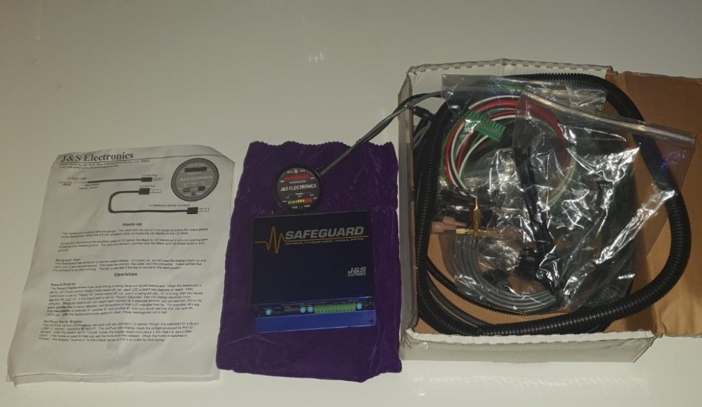
_________________ Carl Johansson 
|
||||||
|
Vilken version är det? Vilken typ av knacksensor använder den?
_________________ Cédric Nyberg Porsche 924 Turbo Toyota GT86 Formel Vee Veemax MKIVB 1970 www.instagram.com/garagecedric/
|
||||||
Perfekt, då tar jag den! Skickar PM strax! _________________ Cédric Nyberg Porsche 924 Turbo Toyota GT86 Formel Vee Veemax MKIVB 1970 www.instagram.com/garagecedric/
|
||||||
Tack, då håller jag koll på inboxen 
_________________ Carl Johansson
|
||||||
|
SÄLJES
SÅLD: Ny J&S Knacksensor Kit (Universal + Miata)
|
2 besök senaste veckan (367 totalt) |