|
Magnus Thomé
Stockholm
Här sen Nov 2002
Inlägg: 41618

Forumägare
Trådstartare

05 Aug 2019 21:29
Copied from https://grassrootsmotorsports.com/forum/grm/diy-stupidly-cheap-tire-te . . . .
--------------------------------------------------------------------------------------------------------------------------
Yay, nice to hear more people building these :-)
My replies mixed with your questions here below:
I must admit that I have not completely understood what the optional distance sensor is intended for: is it somehow used to aid internal temperature calculations of the moving wheel, or is it rather an actual separate measure for damper movement (e.g. for detecting roll)? If the latter, it would only make sense if the sensor is mounted completely pointing straight top-down onto the top of the tire, right?
Yes, totally separate just to get movement. You can simply skip it. And yes, straight top down hitting the very top of the wheel is best but aiming at an angle will still get you data, just slightly scaled. Also take note that turning the wheel might change the distance depending on caster, camber gain and so on depending on what spot on the tire you measure on.
Re the sandwich mount: is it supposed to house the two sensors and be connected to the Mainboard using waterproof automotive-grade cable connectors?
If you use the mainboard I designed they are soldered together directly with no cables at all. There are a series of pictures showing how all the parts are mounted together here https://github.com/MagnusThome/RejsaRubberTrac/tree/master/pcb
What is the practical limit of # BT devices in such environments? GPS, Camera, 4x RRT, TPMS. That is quite a lot. Is this an issue?
Antti at Racechrono has done performance testing and with much slower older hardware in your phone you might get reduced data update rates in a worst case scenario. I noticed that running OBD2 + GPS + 2 RRT + Video worked flawlessly on my quite old OnePlus One. BUT if I at the same time played music or took a phone call over bluetooth that sound would cut out a bit.
How are the sensors calibrated? How do I tell e.g. HLT where the wheel ends? How is the damper travel for the distance sensor normalized to 0-100%?
You need to aim the sensor correctly. I have a resistor that I run some current through from a USB powerbank, then I move the hot resistor in the sensors field of view on the tire to aim the sensor correctly. If you place the sensor so it overshoots a bit, catching temperatures outside the sides of the tire you'll easily see when driving on track where the tire edges are due to the huge temperature drop in the display. But I have mine aimed correctly, the outer color bars in the display exactly matching the outer edges of the tires.
The distance sensor shows the distance to the tire in millimeters. There is an option to add an offset in the software code if you want it to show 0mm when the car is stationary on flat level ground and then show the movement with positive and negative distance values instead. But you really will never get a 100% perfect zero when stationary since this will change slightly with amount of fuel, driver, tire wear, unleveled ground and just tolerances in the chassis.
Did you ever consider an additional separate temperature sensor to measure tarmac temps for the corresponding section of the track?
No :-) That could be a one single point measurement though. Or simply aim the sensor so the outer color bars aim at, and show, the tarmac temp!
Would it work using only one mainboard per axle and connecting two sensors to it? This would reduce both active BT devices and components necessary. Or are limitations in computing power an issue here?
The load on the phone is rather on the total amount of data transferred and that would be the same. I do think it would lower the load slightly but not enough to warrant the design change. And personally I wanted to stay away from any external cables.
IR transparent film for the lens: can I test IR transparency with a TV remote control? I have some old used motorcycle visor "Pinlock" screens that have some scratches somewhere but enough "good" areas to cut something out as lens protection. They are visually excellent and I would hope that IR would pass through...
Sorry, I don't know. Try it!
Still need to make more precise measures, but I would assume we need 120 degree "-BAA" FOV sensors. Did you ever come across some of these _with_ daughter board? I did not find them on AliExpress at all, as these are all "-BAB" sensors. On the other hand: without daughter board, how would I fit them in the sandwich mount?
No, I have never seen 120 degrees FOV on a small board :-( But it's easy to solder the sensor sans daughter board directly onto the mainboard that I designed just using the sensors own long legs to mount it a bit above the board when soldering it onto it.
Have you ever considered this unit? It is about a fifth of the price of the Bluefruit and has similar specs, yet an exotic CPU: LOLIN D32 V1.0.0 - wifi & bluetooth board based ESP-32 esp32 ESP-WROOM-32 4MB FLASH Arduino MicroPython Compatible: https://s.click.aliexpress.com/e/bxFE5Mc0 and https://wiki.wemos.cc/products:d32:d32
Yes, it was the cpu I aimed for initially! But the bluetooth BLE was very unstable with all the libraries I tried and after a lot of hours I put it aside. Old school bluetooth (non BLE) works great on it but that didn't help me. I haven't given up on it totally, I might give it another shot someday but that is in the future.
Are there any known issues with fitting the unit on the inside of the wheelhouses (given enough space for the wheel to move of course)? At your M2 you have fitted them above/outside the wheelhouses pointing through a hole. I do not think this is feasible here...
It's just the distance to the tire with the FOV you have which is important really. There is normally good space to mount and ample distance to the tire up in the shock tower but I didn't find any 100% nice way to mount it there with a snap-in/out holder. Tried strong magnets but it didn't work out well on my particular car.
What is your experience with the front axle steering movements of the wheels? Is it actually sufficient to have the sensor mounted statically?
Yes absolutely, if you mount it aiming at the top of the tire from straight above it is not a problem. Well... not for a drifter car with huuuuge steering angles. But for a racing or trackday car, yes. Of course each car's specific steering / front axle geometry can affect this theoretically but with normal steering angles and normal suspension movements it works well.
Is it an option to mount the distance sensor directly on the damper?
The distance sensor can be connected with external wires of course and mounted anywhere, separate from the thermal camera sensor. Just an issue of cables and housings that needs to be done..
P.S.: Registration failed on your forum multiple times for me at rejsa.nu...
Mail me at magnust@gmail.com and I'll set it up for you. I know it's far from optimal with all the Swedish language when trying to register, sorry! I'll copy this post and add it there so we can continue there if you want :-)
_________________  Magnus Thomé
|
_TS
Här sen Aug 2019
Inlägg: 9
07 Aug 2019 03:39
| Magnus Thomé skrev: | ...
Re the sandwich mount: is it supposed to house the two sensors and be connected to the Mainboard using waterproof automotive-grade cable connectors?
If you use the mainboard I designed they are soldered together directly with no cables at all. There are a series of pictures showing how all the parts are mounted together here https://github.com/MagnusThome/RejsaRubberTrac/tree/master/pcb
|
Not sure if we are talking about the same thing. I was referring to what you call "separate sensor enclosure". I was assuming that your mainboard PCB does not fit in there? How would I put a 120 degree sensor lacking a daughter board in there?
| Magnus Thomé skrev: |
How are the sensors calibrated? How do I tell e.g. HLT where the wheel ends? How is the damper travel for the distance sensor normalized to 0-100%?
You need to aim the sensor correctly. I have a resistor that I run some current through from a USB powerbank, then I move the hot resistor in the sensors field of view on the tire to aim the sensor correctly. If you place the sensor so it overshoots a bit, catching temperatures outside the sides of the tire you'll easily see when driving on track where the tire edges are due to the huge temperature drop in the display. But I have mine aimed correctly, the outer color bars in the display exactly matching the outer edges of the tires.
...
|
Would you be willing to share what exact type of power resistor you are using?
I still did not fully understand how the distance in your table, say 6 cm, is to be understood. Is this the base distance when the car is standing on an even surface with wheels steered straight to the front? I.e. any compression of the dampers will further reduce the 6 cm, which would be fine? Or is the 6 cm rather the minimum distance to be maintained even at full damper compression? Damper travel can be significant if ~6 cm is the measure.
| Magnus Thomé skrev: |
Did you ever consider an additional separate temperature sensor to measure tarmac temps for the corresponding section of the track?
No :-) That could be a one single point measurement though. Or simply aim the sensor so the outer color bars aim at, and show, the tarmac temp!
|
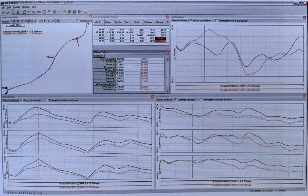
Actually, I find this quite interesting. I am attaching a screenshot found in this excellent book (Fahrdynamik in Perfektion: Der Weg zum optimalen Fahrwerks-Setup; https://www.amazon.de/dp/3613040670/ref=cm_sw_r_cp_api_i_fLJsDbW4KHXHP . . . . unfortunately in German). They are analyzing tire temps for a lap on the Nordschleife with very similar methods compared to RRT. The two lower graphs are outer-center-inner tread temp per each side. The upper right graph is the asphalt/tarmac temperature. You can see deltas of the tarmac of almost 30 degrees C.
If I had one wish for the next version of RRT, then this would be it: a separate one-datapoint IR Sensor optionally to be attached to one of the four RRT boards and to be pointed at the tarmac, transmitting the temperature as a separate time stamped (and therefore GPS-located) value.
| Magnus Thomé skrev: |
Would it work using only one mainboard per axle and connecting two sensors to it? This would reduce both active BT devices and components necessary. Or are limitations in computing power an issue here?
The load on the phone is rather on the total amount of data transferred and that would be the same. I do think it would lower the load slightly but not enough to warrant the design change. And personally I wanted to stay away from any external cables.
|
I was more referring to the load on the microprocessor or it's I2C bus, than to the phone.
| Magnus Thomé skrev: |
IR transparent film for the lens: can I test IR transparency with a TV remote control? I have some old used motorcycle visor "Pinlock" screens that have some scratches somewhere but enough "good" areas to cut something out as lens protection. They are visually excellent and I would hope that IR would pass through...
Sorry, I don't know. Try it!
|
I just had another idea that might be even more neat and reproducible for others: why not use a GoPro gorilla glass lens replacement for a few EUR from AliExpress? It would be quite stable and easy to clean. Also, in case the sensor stays installed permanently, there are silicone caps available for protection during times of non-use.
EUR 5,66 UV Lens Ring Replacement Protective Repair Case Frame for Gopro Hero 5/6/7 Black
https://s.click.aliexpress.com/e/qKddyYu
One would need to replicate the shape of the front of the GoPro in the 3D-Print as the lens seems to be turn-clicked to be put into place. But I think that would not be the actual problem. I do not have the corresponding GoPro atm. But that should be solvable. Could you maybe measure what diameter would be needed to fit both sensors behind the same round shape glass cover?
| Magnus Thomé skrev: |
Have you ever considered this unit? It is about a fifth of the price of the Bluefruit and has similar specs, yet an exotic CPU: LOLIN D32 V1.0.0 - wifi & bluetooth board based ESP-32 esp32 ESP-WROOM-32 4MB FLASH Arduino MicroPython Compatible: https://s.click.aliexpress.com/e/bxFE5Mc0 and https://wiki.wemos.cc/products:d32:d32
Yes, it was the cpu I aimed for initially! But the bluetooth BLE was very unstable with all the libraries I tried and after a lot of hours I put it aside. Old school bluetooth (non BLE) works great on it but that didn't help me. I haven't given up on it totally, I might give it another shot someday but that is in the future.
|
Understood. The other board with a similar price tag that I found is this one. It lacks a battery charger but is also a bit smaller. Did you try this one as well?
EUR 7,12 Keywish BLE-Nano for Arduino Nano V3.0 Mirco USB Board Integrate CC2540 BLE Wireless Module ATmega328P Micro-Controller Board
https://s.click.aliexpress.com/e/bxQ2RJtA
| Magnus Thomé skrev: |
Are there any known issues with fitting the unit on the inside of the wheelhouses (given enough space for the wheel to move of course)? At your M2 you have fitted them above/outside the wheelhouses pointing through a hole. I do not think this is feasible here...
It's just the distance to the tire with the FOV you have which is important really. There is normally good space to mount and ample distance to the tire up in the shock tower but I didn't find any 100% nice way to mount it there with a snap-in/out holder. Tried strong magnets but it didn't work out well on my particular car.
|
I do believe I will need to think about a new design for an enclosure that is suitable for permanent installation in the wheel housing. I am thinking about a ball-shaped enclosing for all components (not just the sensors) to be embedded in a cutout of the inner wheel housing. Using the ball-shaped enclosure and an outer ring that compresses and keeps the ball's position, it should still allow for some reasonable adjustment of angle once in place in the cutout.
Just to get a basic understanding of the FOV angles necessary for fine tuning: if I start from a position straight down and find out that I need to position further away: if straight down is 0 degrees, is it a fair assumption that with not changing the sensor's position, but only it's angle, within -45-0-45 degrees one would find the optimal angle? Maybe even within -35-0-35 degrees?
Also I would like to have the RRT battery accessible without having to tear apart half of the car. Let's say I do not exactly trust the cheap Lipo batteries for the long term. I would pay way more for some really good quality LiPo and peace of mind, but would not know where to source from.
Thanks,
TS
_________________
Torben Schreiter
|
Magnus Thomé
Stockholm
Här sen Nov 2002
Inlägg: 41618
Forumägare
Trådstartare
07 Aug 2019 09:02
| _TS skrev: | | Magnus Thomé skrev: | ...
Re the sandwich mount: is it supposed to house the two sensors and be connected to the Mainboard using waterproof automotive-grade cable connectors?
If you use the mainboard I designed they are soldered together directly with no cables at all. There are a series of pictures showing how all the parts are mounted together here https://github.com/MagnusThome/RejsaRubberTrac/tree/master/pcb
|
Not sure if we are talking about the same thing. I was referring to what you call "separate sensor enclosure". I was assuming that your mainboard PCB does not fit in there? How would I put a 120 degree sensor lacking a daughter board in there?
Ahhh, misunderstood "sandwich" totally. Hmmm... well, you have a good question there. It's totally doable but it gets a bit fiddly. If you take the large mainboard I made and cut it down you get a board that works as the missing tempsensor daugther board including the pin holes that connect to the distance sensor board. I'll make some instruction photos for this 
| Magnus Thomé skrev: |
How are the sensors calibrated? How do I tell e.g. HLT where the wheel ends? How is the damper travel for the distance sensor normalized to 0-100%?
You need to aim the sensor correctly. I have a resistor that I run some current through from a USB powerbank, then I move the hot resistor in the sensors field of view on the tire to aim the sensor correctly. If you place the sensor so it overshoots a bit, catching temperatures outside the sides of the tire you'll easily see when driving on track where the tire edges are due to the huge temperature drop in the display. But I have mine aimed correctly, the outer color bars in the display exactly matching the outer edges of the tires.
...
|
Would you be willing to share what exact type of power resistor you are using?
With a 5 volt power bank: 22 ohm 1 watt.
I still did not fully understand how the distance in your table, say 6 cm, is to be understood. Is this the base distance when the car is standing on an even surface with wheels steered straight to the front? I.e. any compression of the dampers will further reduce the 6 cm, which would be fine? Or is the 6 cm rather the minimum distance to be maintained even at full damper compression? Damper travel can be significant if ~6 cm is the measure.
It's the distance to the tire when the full width of the tire is visible. When the tire gets closer the sensor will not see the full tire width. Important note, a 120 degree sensor is way more sensitive to suspension movement than the 60 degree one due to being so much closer. It really comes down to what precision one is aiming for. If you want a more precise location of the tire in the field of view I'd suggest mounting the sensor camera on the suspension as you mentioned earlier elsewhere For less precise measurements mounting it to the wheel well works fine, you get a rough idea what you get from this looking at some of my videos  ( https://www.youtube.com/user/magnusthome ) ( https://www.youtube.com/user/magnusthome )
| Magnus Thomé skrev: |
Did you ever consider an additional separate temperature sensor to measure tarmac temps for the corresponding section of the track?
No :-) That could be a one single point measurement though. Or simply aim the sensor so the outer color bars aim at, and show, the tarmac temp!
|
Actually, I find this quite interesting. I am attaching a screenshot found in this excellent book (Fahrdynamik in Perfektion: Der Weg zum optimalen Fahrwerks-Setup; https://www.amazon.de/dp/3613040670/ref=cm_sw_r_cp_api_i_fLJsDbW4KHXHP . . . . unfortunately in German). They are analyzing tire temps for a lap on the Nordschleife with very similar methods compared to RRT. The two lower graphs are outer-center-inner tread temp per each side. The upper right graph is the asphalt/tarmac temperature. You can see deltas of the tarmac of almost 30 degrees C.
If I had one wish for the next version of RRT, then this would be it: a separate one-datapoint IR Sensor optionally to be attached to one of the four RRT boards and to be pointed at the tarmac, transmitting the temperature as a separate time stamped (and therefore GPS-located) value.
I'll keep this in mind, it's doable. But I don't have any near time plans for a major revision of the kit currently. There can possibly be a problem that adding this would push the data update rate for all sensors further down though.
[ig]https://rejsa.nu/im/user/27937/2019-08-07-04-21-52_dbf50742-6c0b-4c90-9b17-2cff2cdb802a.jpeg[/img]
| Magnus Thomé skrev: |
Would it work using only one mainboard per axle and connecting two sensors to it? This would reduce both active BT devices and components necessary. Or are limitations in computing power an issue here?
The load on the phone is rather on the total amount of data transferred and that would be the same. I do think it would lower the load slightly but not enough to warrant the design change. And personally I wanted to stay away from any external cables.
|
I was more referring to the load on the microprocessor or it's I2C bus, than to the phone.
Yeah, I was very unclear, currently the bottleneck is the bluetooth BLE data transfer rate plus the delay getting the data from the sensors with the current libraries used. When the phone collects two data packets instead of one data packet per reading ( https://github.com/MagnusThome/RejsaRubberTrac#how-often-can-i-get-mea . . . . ) there is a considerable delay added for example. A major dig into the libraries could probably make it possible to get higher data rates both over BLE and from the sensors. Obviously not 100% sure but I don't think the limits are in either cpu or i2c but how the libraries are done. But since this setup works I was happy I didn't need to spend time digging into the inners of the libraries
| Magnus Thomé skrev: |
IR transparent film for the lens: can I test IR transparency with a TV remote control? I have some old used motorcycle visor "Pinlock" screens that have some scratches somewhere but enough "good" areas to cut something out as lens protection. They are visually excellent and I would hope that IR would pass through...
Sorry, I don't know. Try it!
|
I just had another idea that might be even more neat and reproducible for others: why not use a GoPro gorilla glass lens replacement for a few EUR from AliExpress? It would be quite stable and easy to clean. Also, in case the sensor stays installed permanently, there are silicone caps available for protection during times of non-use.
EUR 5,66 UV Lens Ring Replacement Protective Repair Case Frame for Gopro Hero 5/6/7 Black
https://s.click.aliexpress.com/e/qKddyYu
One would need to replicate the shape of the front of the GoPro in the 3D-Print as the lens seems to be turn-clicked to be put into place. But I think that would not be the actual problem. I do not have the corresponding GoPro atm. But that should be solvable. Could you maybe measure what diameter would be needed to fit both sensors behind the same round shape glass cover?
That would be very nice! But I'm a bit pessimistic that the IR camera will "see" through it. But WELL worth a try! The Gopro window square window is large enough to work. The round smaller one on the link is probably to small though.
One important note, the distance and temperature sensors have very different "needs" when it comes to what they can see through. The distance sensor will not be able to measure through anything that reflects light back from the sender to the receiver. Either the sender and receiver light paths need to be separated so light can't be reflected and "shorted" back by for example two tubes up against the glass. Or one simply needs to put the sensor chip right up against the glass, also preventing any light reflecting back. My experience is that two tubes adds noise to the distance measurements and also limits the max range measurable. Depending on diameter of the tubes, probably length too.
| Magnus Thomé skrev: |
Have you ever considered this unit? It is about a fifth of the price of the Bluefruit and has similar specs, yet an exotic CPU: LOLIN D32 V1.0.0 - wifi & bluetooth board based ESP-32 esp32 ESP-WROOM-32 4MB FLASH Arduino MicroPython Compatible: https://s.click.aliexpress.com/e/bxFE5Mc0 and https://wiki.wemos.cc/products:d32:d32
Yes, it was the cpu I aimed for initially! But the bluetooth BLE was very unstable with all the libraries I tried and after a lot of hours I put it aside. Old school bluetooth (non BLE) works great on it but that didn't help me. I haven't given up on it totally, I might give it another shot someday but that is in the future.
|
Understood. The other board with a similar price tag that I found is this one. It lacks a battery charger but is also a bit smaller. Did you try this one as well?
EUR 7,12 Keywish BLE-Nano for Arduino Nano V3.0 Mirco USB Board Integrate CC2540 BLE Wireless Module ATmega328P Micro-Controller Board
https://s.click.aliexpress.com/e/bxQ2RJtA
Very nice find!!! Never seen that one before. I've been looking for a cheaper cpu+ble solution since the current board is very pricey. I have a nRF board with no auxilaries here but would need to make a new mainboard for it... I'll order that one you found to look at it 
| Magnus Thomé skrev: |
Are there any known issues with fitting the unit on the inside of the wheelhouses (given enough space for the wheel to move of course)? At your M2 you have fitted them above/outside the wheelhouses pointing through a hole. I do not think this is feasible here...
It's just the distance to the tire with the FOV you have which is important really. There is normally good space to mount and ample distance to the tire up in the shock tower but I didn't find any 100% nice way to mount it there with a snap-in/out holder. Tried strong magnets but it didn't work out well on my particular car.
|
I do believe I will need to think about a new design for an enclosure that is suitable for permanent installation in the wheel housing. I am thinking about a ball-shaped enclosing for all components (not just the sensors) to be embedded in a cutout of the inner wheel housing. Using the ball-shaped enclosure and an outer ring that compresses and keeps the ball's position, it should still allow for some reasonable adjustment of angle once in place in the cutout.
Just to get a basic understanding of the FOV angles necessary for fine tuning: if I start from a position straight down and find out that I need to position further away: if straight down is 0 degrees, is it a fair assumption that with not changing the sensor's position, but only it's angle, within -45-0-45 degrees one would find the optimal angle? Maybe even within -35-0-35 degrees?
Well, you'd have to do like me, dig into the trigometri I forgot from school hehe. If you have your base aim exactly 90 degrees against the tire you will need much higher angles to change the distance to the tire than if your base aim is say 60-70 degrees againts the tire. This probably makes more sense if you draw a picture instead of reading my half ass explanation
Also I would like to have the RRT battery accessible without having to tear apart half of the car. Let's say I do not exactly trust the cheap Lipo batteries for the long term. I would pay way more for some really good quality LiPo and peace of mind, but would not know where to source from.
I wanted to totally stay away from cables. But if you possibly don't mind cables, why not use the car 12V? Or a power bank. I had low charge one day and simply put a power bank in the engine compartment and two usb cables. Temporary but it worked very nicely
Thanks,
TS |
_________________ Magnus Thomé
|
Magnus Thomé
Stockholm
Här sen Nov 2002
Inlägg: 41618
Forumägare
Trådstartare
07 Aug 2019 13:54
_________________ Magnus Thomé
|
_TS
Här sen Aug 2019
Inlägg: 9
09 Sep 2019 07:21
Hi Magnus,
sorry for the long quiet time. Please see for some replies below.
| Magnus Thomé skrev: | | Magnus Thomé skrev: | ...
Re the sandwich mount: is it supposed to house the two sensors and be connected to the Mainboard using waterproof automotive-grade cable connectors?
If you use the mainboard I designed they are soldered together directly with no cables at all. There are a series of pictures showing how all the parts are mounted together here https://github.com/MagnusThome/RejsaRubberTrac/tree/master/pcb
|
Not sure if we are talking about the same thing. I was referring to what you call "separate sensor enclosure". I was assuming that your mainboard PCB does not fit in there? How would I put a 120 degree sensor lacking a daughter board in there?
Ahhh, misunderstood "sandwich" totally. Hmmm... well, you have a good question there. It's totally doable but it gets a bit fiddly. If you take the large mainboard I made and cut it down you get a board that works as the missing tempsensor daugther board including the pin holes that connect to the distance sensor board. I'll make some instruction photos for this
|
Understood, thanks.
| Magnus Thomé skrev: |
| Magnus Thomé skrev: |
How are the sensors calibrated? How do I tell e.g. HLT where the wheel ends? How is the damper travel for the distance sensor normalized to 0-100%?
You need to aim the sensor correctly. I have a resistor that I run some current through from a USB powerbank, then I move the hot resistor in the sensors field of view on the tire to aim the sensor correctly. If you place the sensor so it overshoots a bit, catching temperatures outside the sides of the tire you'll easily see when driving on track where the tire edges are due to the huge temperature drop in the display. But I have mine aimed correctly, the outer color bars in the display exactly matching the outer edges of the tires.
...
|
Would you be willing to share what exact type of power resistor you are using?
With a 5 volt power bank: 22 ohm 1 watt.
|
Thanks, I have ordered some from China. They have arrived in the meantime. Will solder a USB plug to them soon.
| Magnus Thomé skrev: |
I still did not fully understand how the distance in your table, say 6 cm, is to be understood. Is this the base distance when the car is standing on an even surface with wheels steered straight to the front? I.e. any compression of the dampers will further reduce the 6 cm, which would be fine? Or is the 6 cm rather the minimum distance to be maintained even at full damper compression? Damper travel can be significant if ~6 cm is the measure.
It's the distance to the tire when the full width of the tire is visible. When the tire gets closer the sensor will not see the full tire width. Important note, a 120 degree sensor is way more sensitive to suspension movement than the 60 degree one due to being so much closer. It really comes down to what precision one is aiming for. If you want a more precise location of the tire in the field of view I'd suggest mounting the sensor camera on the suspension as you mentioned earlier elsewhere For less precise measurements mounting it to the wheel well works fine, you get a rough idea what you get from this looking at some of my videos ( https://www.youtube.com/user/magnusthome )
|
So, to confirm, it is the minimum distance, i.e. at full damper compression, correct?
| Magnus Thomé skrev: |
| Magnus Thomé skrev: |
IR transparent film for the lens: can I test IR transparency with a TV remote control? I have some old used motorcycle visor "Pinlock" screens that have some scratches somewhere but enough "good" areas to cut something out as lens protection. They are visually excellent and I would hope that IR would pass through...
Sorry, I don't know. Try it!
|
I just had another idea that might be even more neat and reproducible for others: why not use a GoPro gorilla glass lens replacement for a few EUR from AliExpress? It would be quite stable and easy to clean. Also, in case the sensor stays installed permanently, there are silicone caps available for protection during times of non-use.
EUR 5,66 UV Lens Ring Replacement Protective Repair Case Frame for Gopro Hero 5/6/7 Black
https://s.click.aliexpress.com/e/qKddyYu
One would need to replicate the shape of the front of the GoPro in the 3D-Print as the lens seems to be turn-clicked to be put into place. But I think that would not be the actual problem. I do not have the corresponding GoPro atm. But that should be solvable. Could you maybe measure what diameter would be needed to fit both sensors behind the same round shape glass cover?
That would be very nice! But I'm a bit pessimistic that the IR camera will "see" through it. But WELL worth a try! The Gopro window square window is large enough to work. The round smaller one on the link is probably to small though.
One important note, the distance and temperature sensors have very different "needs" when it comes to what they can see through. The distance sensor will not be able to measure through anything that reflects light back from the sender to the receiver. Either the sender and receiver light paths need to be separated so light can't be reflected and "shorted" back by for example two tubes up against the glass. Or one simply needs to put the sensor chip right up against the glass, also preventing any light reflecting back. My experience is that two tubes adds noise to the distance measurements and also limits the max range measurable. Depending on diameter of the tubes, probably length too.
|
Have ordered one to test, which has arrived some days ago. While I do not have a MLX90621, yet, I have tested its infrared transparency using my standalone handheld infrared thermometer. It is, unfortunately, not transparent for that one. So, I assume any MLX90621 won't be able to see through it either. Too bad, would have been a nice solution... 
| Magnus Thomé skrev: |
| Magnus Thomé skrev: |
Have you ever considered this unit? It is about a fifth of the price of the Bluefruit and has similar specs, yet an exotic CPU: LOLIN D32 V1.0.0 - wifi & bluetooth board based ESP-32 esp32 ESP-WROOM-32 4MB FLASH Arduino MicroPython Compatible: https://s.click.aliexpress.com/e/bxFE5Mc0 and https://wiki.wemos.cc/products:d32:d32
Yes, it was the cpu I aimed for initially! But the bluetooth BLE was very unstable with all the libraries I tried and after a lot of hours I put it aside. Old school bluetooth (non BLE) works great on it but that didn't help me. I haven't given up on it totally, I might give it another shot someday but that is in the future.
|
Understood. The other board with a similar price tag that I found is this one. It lacks a battery charger but is also a bit smaller. Did you try this one as well?
EUR 7,12 Keywish BLE-Nano for Arduino Nano V3.0 Mirco USB Board Integrate CC2540 BLE Wireless Module ATmega328P Micro-Controller Board
https://s.click.aliexpress.com/e/bxQ2RJtA
Very nice find!!! Never seen that one before. I've been looking for a cheaper cpu+ble solution since the current board is very pricey. I have a nRF board with no auxilaries here but would need to make a new mainboard for it... I'll order that one you found to look at it
|
I had also ordered one from China, which has arrived in the meantime along with a distance sensor. I have not yet had the time to flash it. Have you had any chance already to try if it indeed works?
| Magnus Thomé skrev: |
| Magnus Thomé skrev: |
Are there any known issues with fitting the unit on the inside of the wheelhouses (given enough space for the wheel to move of course)? At your M2 you have fitted them above/outside the wheelhouses pointing through a hole. I do not think this is feasible here...
It's just the distance to the tire with the FOV you have which is important really. There is normally good space to mount and ample distance to the tire up in the shock tower but I didn't find any 100% nice way to mount it there with a snap-in/out holder. Tried strong magnets but it didn't work out well on my particular car.
|
I do believe I will need to think about a new design for an enclosure that is suitable for permanent installation in the wheel housing. I am thinking about a ball-shaped enclosing for all components (not just the sensors) to be embedded in a cutout of the inner wheel housing. Using the ball-shaped enclosure and an outer ring that compresses and keeps the ball's position, it should still allow for some reasonable adjustment of angle once in place in the cutout.
Just to get a basic understanding of the FOV angles necessary for fine tuning: if I start from a position straight down and find out that I need to position further away: if straight down is 0 degrees, is it a fair assumption that with not changing the sensor's position, but only it's angle, within -45-0-45 degrees one would find the optimal angle? Maybe even within -35-0-35 degrees?
Well, you'd have to do like me, dig into the trigometri I forgot from school hehe. If you have your base aim exactly 90 degrees against the tire you will need much higher angles to change the distance to the tire than if your base aim is say 60-70 degrees againts the tire. This probably makes more sense if you draw a picture instead of reading my half ass explanation
|
That's clear. Can you still give me a short overview which of the two sensors (60 or 120 degrees) at what two distance extremes (i.e. normal vs compressed dampers) at what angle you have mounted at your M2? Just to get some inspiration.
Also I am glad that the idea of the autozoom for the sensor came up in the meantime in the other thread, as I was thinking about sth similar. With the 120 degree sensor I somehow doubt, it can be statically fixed/adjusted for full damper travel to fit the FOV in all occasions.
Cheers and thanks,
TS
_________________
Torben Schreiter
|
Magnus Thomé
Stockholm
Här sen Nov 2002
Inlägg: 41618
Forumägare
Trådstartare
09 Sep 2019 09:47
Hi Magnus,
sorry for the long quiet time. Please see for some replies below.
| Magnus Thomé skrev: | | Magnus Thomé skrev: | ...
Re the sandwich mount: is it supposed to house the two sensors and be connected to the Mainboard using waterproof automotive-grade cable connectors?
If you use the mainboard I designed they are soldered together directly with no cables at all. There are a series of pictures showing how all the parts are mounted together here https://github.com/MagnusThome/RejsaRubberTrac/tree/master/pcb
|
Not sure if we are talking about the same thing. I was referring to what you call "separate sensor enclosure". I was assuming that your mainboard PCB does not fit in there? How would I put a 120 degree sensor lacking a daughter board in there?
Ahhh, misunderstood "sandwich" totally. Hmmm... well, you have a good question there. It's totally doable but it gets a bit fiddly. If you take the large mainboard I made and cut it down you get a board that works as the missing tempsensor daugther board including the pin holes that connect to the distance sensor board. I'll make some instruction photos for this
|
Understood, thanks.
Photos are up on github
| Magnus Thomé skrev: |
| Magnus Thomé skrev: |
How are the sensors calibrated? How do I tell e.g. HLT where the wheel ends? How is the damper travel for the distance sensor normalized to 0-100%?
You need to aim the sensor correctly. I have a resistor that I run some current through from a USB powerbank, then I move the hot resistor in the sensors field of view on the tire to aim the sensor correctly. If you place the sensor so it overshoots a bit, catching temperatures outside the sides of the tire you'll easily see when driving on track where the tire edges are due to the huge temperature drop in the display. But I have mine aimed correctly, the outer color bars in the display exactly matching the outer edges of the tires.
...
|
Would you be willing to share what exact type of power resistor you are using?
With a 5 volt power bank: 22 ohm 1 watt.
|
Thanks, I have ordered some from China. They have arrived in the meantime. Will solder a USB plug to them soon.
| Magnus Thomé skrev: |
I still did not fully understand how the distance in your table, say 6 cm, is to be understood. Is this the base distance when the car is standing on an even surface with wheels steered straight to the front? I.e. any compression of the dampers will further reduce the 6 cm, which would be fine? Or is the 6 cm rather the minimum distance to be maintained even at full damper compression? Damper travel can be significant if ~6 cm is the measure.
It's the distance to the tire when the full width of the tire is visible. When the tire gets closer the sensor will not see the full tire width. Important note, a 120 degree sensor is way more sensitive to suspension movement than the 60 degree one due to being so much closer. It really comes down to what precision one is aiming for. If you want a more precise location of the tire in the field of view I'd suggest mounting the sensor camera on the suspension as you mentioned earlier elsewhere For less precise measurements mounting it to the wheel well works fine, you get a rough idea what you get from this looking at some of my videos ( https://www.youtube.com/user/magnusthome )
|
So, to confirm, it is the minimum distance, i.e. at full damper compression, correct?
Yes.
| Magnus Thomé skrev: |
| Magnus Thomé skrev: |
IR transparent film for the lens: can I test IR transparency with a TV remote control? I have some old used motorcycle visor "Pinlock" screens that have some scratches somewhere but enough "good" areas to cut something out as lens protection. They are visually excellent and I would hope that IR would pass through...
Sorry, I don't know. Try it!
|
I just had another idea that might be even more neat and reproducible for others: why not use a GoPro gorilla glass lens replacement for a few EUR from AliExpress? It would be quite stable and easy to clean. Also, in case the sensor stays installed permanently, there are silicone caps available for protection during times of non-use.
EUR 5,66 UV Lens Ring Replacement Protective Repair Case Frame for Gopro Hero 5/6/7 Black
https://s.click.aliexpress.com/e/qKddyYu
One would need to replicate the shape of the front of the GoPro in the 3D-Print as the lens seems to be turn-clicked to be put into place. But I think that would not be the actual problem. I do not have the corresponding GoPro atm. But that should be solvable. Could you maybe measure what diameter would be needed to fit both sensors behind the same round shape glass cover?
That would be very nice! But I'm a bit pessimistic that the IR camera will "see" through it. But WELL worth a try! The Gopro window square window is large enough to work. The round smaller one on the link is probably to small though.
One important note, the distance and temperature sensors have very different "needs" when it comes to what they can see through. The distance sensor will not be able to measure through anything that reflects light back from the sender to the receiver. Either the sender and receiver light paths need to be separated so light can't be reflected and "shorted" back by for example two tubes up against the glass. Or one simply needs to put the sensor chip right up against the glass, also preventing any light reflecting back. My experience is that two tubes adds noise to the distance measurements and also limits the max range measurable. Depending on diameter of the tubes, probably length too.
|
Have ordered one to test, which has arrived some days ago. While I do not have a MLX90621, yet, I have tested its infrared transparency using my standalone handheld infrared thermometer. It is, unfortunately, not transparent for that one. So, I assume any MLX90621 won't be able to see through it either. Too bad, would have been a nice solution...
Good you tried anyway, it'd be great if some alternative is found
| Magnus Thomé skrev: |
| Magnus Thomé skrev: |
Have you ever considered this unit? It is about a fifth of the price of the Bluefruit and has similar specs, yet an exotic CPU: LOLIN D32 V1.0.0 - wifi & bluetooth board based ESP-32 esp32 ESP-WROOM-32 4MB FLASH Arduino MicroPython Compatible: https://s.click.aliexpress.com/e/bxFE5Mc0 and https://wiki.wemos.cc/products:d32:d32
Yes, it was the cpu I aimed for initially! But the bluetooth BLE was very unstable with all the libraries I tried and after a lot of hours I put it aside. Old school bluetooth (non BLE) works great on it but that didn't help me. I haven't given up on it totally, I might give it another shot someday but that is in the future.
|
Understood. The other board with a similar price tag that I found is this one. It lacks a battery charger but is also a bit smaller. Did you try this one as well?
EUR 7,12 Keywish BLE-Nano for Arduino Nano V3.0 Mirco USB Board Integrate CC2540 BLE Wireless Module ATmega328P Micro-Controller Board
https://s.click.aliexpress.com/e/bxQ2RJtA
Very nice find!!! Never seen that one before. I've been looking for a cheaper cpu+ble solution since the current board is very pricey. I have a nRF board with no auxilaries here but would need to make a new mainboard for it... I'll order that one you found to look at it
|
I had also ordered one from China, which has arrived in the meantime along with a distance sensor. I have not yet had the time to flash it. Have you had any chance already to try if it indeed works?
Hasn't arrived so not yet. But the BLE library would be different I suppose.
| Magnus Thomé skrev: |
| Magnus Thomé skrev: |
Are there any known issues with fitting the unit on the inside of the wheelhouses (given enough space for the wheel to move of course)? At your M2 you have fitted them above/outside the wheelhouses pointing through a hole. I do not think this is feasible here...
It's just the distance to the tire with the FOV you have which is important really. There is normally good space to mount and ample distance to the tire up in the shock tower but I didn't find any 100% nice way to mount it there with a snap-in/out holder. Tried strong magnets but it didn't work out well on my particular car.
|
I do believe I will need to think about a new design for an enclosure that is suitable for permanent installation in the wheel housing. I am thinking about a ball-shaped enclosing for all components (not just the sensors) to be embedded in a cutout of the inner wheel housing. Using the ball-shaped enclosure and an outer ring that compresses and keeps the ball's position, it should still allow for some reasonable adjustment of angle once in place in the cutout.
Just to get a basic understanding of the FOV angles necessary for fine tuning: if I start from a position straight down and find out that I need to position further away: if straight down is 0 degrees, is it a fair assumption that with not changing the sensor's position, but only it's angle, within -45-0-45 degrees one would find the optimal angle? Maybe even within -35-0-35 degrees?
Well, you'd have to do like me, dig into the trigometri I forgot from school hehe. If you have your base aim exactly 90 degrees against the tire you will need much higher angles to change the distance to the tire than if your base aim is say 60-70 degrees againts the tire. This probably makes more sense if you draw a picture instead of reading my half ass explanation
|
That's clear. Can you still give me a short overview which of the two sensors (60 or 120 degrees) at what two distance extremes (i.e. normal vs compressed dampers) at what angle you have mounted at your M2? Just to get some inspiration.
My sensors are 120 degree ones and should be moved away about a cm more from the tire to be optimally placed, they are currently at about 9-10cm and suspension travel is about 3-4cm. But for now I've gone for a "good enough" approach. Since they are aimed exactly straight down at the very top of the tires, hitting them at an 90 degree angle I could also instead change the angle but since they are at 90 degrees I'd need to angle them quite a lot before I'd get the added 1cm or so distance I need. This would also make them hit the tire quite a far way from the very top of them so this isn't optimal. So either move them further straight up about a cm or move the mounting position completely further back in the wheel well, still aiming very close to the top of the tire but at an angle like in the drawing on github
https://raw.githubusercontent.com/MagnusThome/RejsaRubberTrac/master/i . . . .
Also I am glad that the idea of the autozoom for the sensor came up in the meantime in the other thread, as I was thinking about sth similar. With the 120 degree sensor I somehow doubt, it can be statically fixed/adjusted for full damper travel to fit the FOV in all occasions.
Cheers and thanks,
TS
_________________ Magnus Thomé
|
_TS
Här sen Aug 2019
Inlägg: 9
09 Sep 2019 10:59
Hi Magnus,
still trying to understand the applicability of the 120 degrees sensor. Let's say we go for 195 tires front (as on my Elise). Then we would go for 60mm distance at full damper compression. Let's assume a total of another 60mm of wheel travel. I.e. if the wheel is without any weight the maximum distance would be 120mm (e.g. mid-jump or inner corner wheel at very high G).
Trigonometry says:
distance 60mm @120deg => width = ~208mm
distance 120mm @120deg => width = ~416mm
How would that ever work? Over the course of a lap, the outer tire shoulders will never be captured by the identical sensor regions at the angle, would they? At least not without any software adjustment. What is your thought on this?
Cheers and thanks,
TS
_________________
Torben Schreiter
|
Magnus Thomé
Stockholm
Här sen Nov 2002
Inlägg: 41618
Forumägare
Trådstartare
09 Sep 2019 11:21
You are right that whatever you do the tire will move within the field of view. It's mainly a question on how much movement you can accept and still think data will help you.
120 degree will never be a good option on suspension with a lot of travel. And on narrow tires this gets even worse.
I have wider tires (265) and the M2 on track has quite a limited suspension travel.
A 60 degree sensor is always absolute best option to follow any width of tire during suspension travel. But with very wide tires mounting position can be a problem to accomplish due to the neccessary distance needed.
_________________ Magnus Thomé
|
_TS
Här sen Aug 2019
Inlägg: 9
27 Sep 2019 19:57
Hi there,
just wanted to share my recent findings on the Keywish BLE Nano unit (make "Emakefun" w/ TI CC2540 radio). I spent several hours to work out how this works. My plan was to port the RRT "dummydata" to the Keywish for starters. Looks like this is not that simple at all.
Findings:
1) Turns out the AT command set is not actually the same amongst "CC2540" radios on the market, but varies significantly by the particular firmware, that is run on the CC2540/2541. The firmware that came with the Keywish/Emakefun seems to be total crap, as it is not supporting any AT commands to have a Central read data in slave mode. It is an extremely limited instruction set that does not allow much.
2) The best firmware for this radio seems to be the official "HM-10" firmware by "Jinan Huamao": http://www.jnhuamao.cn/index_en.asp?ID=1
3) There are crossflash instructions available - originally for cheap clone CC254X boards to run the "original" HM-10 firmware. However, I am still collecting the last bits of information before I will try a crossflash attempt on the one Keywish I have: https://forum.arduino.cc/index.php?topic=393655.0
and
http://www.obddiag.net/ble-adventures.html
4) Even if the crossflash succeeds, then there is still one major problem left: according to the best HM-10 tutorial I found ( http://www.martyncurrey.com/hm-10-bluetooth-4ble-modules/), the CC245X only supports one single GATT characteristic for read access:
| Citat: | By default the HM-10 comes with a single custom characteristic under a custom service and a second write only characteristic one can be added using the "AT+FFE2″ command. "AT+FFE2″ was added in firmware 5.45 and extended in version 5.50.
The second custom characteristic only has a WRITE property no READ and the value of this characteristic is sent to the serial UART connection the same as the FFE1 characteristic. |
You are, however, using three custom characteristics (w/ 20 bytes each) for RRT. That is, as far as I understand, the same data structure for communication will be impossible. Either the data structure is changed to a single, larger characteristic or the HM-10 compatible radios will never work for RRT. I suppose this would also require changes to the client apps (such as HLT), right? Was the use of three characteristics actually an important design decision back then?
Cheers,
TS
_________________
Torben Schreiter
|
Magnus Thomé
Stockholm
Här sen Nov 2002
Inlägg: 41618
Forumägare
Trådstartare
27 Sep 2019 21:18
For low energy bluetooth the max size of the datapacket when using notify or indicate is 20 bytes, hence the multiple packets for 16 int temps. And one packet for 8 temps. Plus battery status and distance value.
I just got my Keywish boards today so I haven't looked into them so far. But the code has already been ported to ESP32 by Mark. ESP32 is a real top choice, Easy to get hold of, available everywhere for 3-4 $
_________________ Magnus Thomé
|
_TS
Här sen Aug 2019
Inlägg: 9
27 Sep 2019 21:22
| Magnus Thomé skrev: | For low energy bluetooth the max size of the datapacket when using notify or indicate is 20 bytes, hence the multiple packets for 16 int temps. And one packet for 8 temps. Plus battery status and distance value.
I just got my Keywish boards today so I haven't looked into them so far. But the code has already been ported to ESP32 by Mark. ESP32 is a real top choice, Easy to get hold of, available everywhere for 3-4 $ |
I also just noticed the ESP32 code in Mark's repo. Was he able to resolve the issues you had earlier? Were they BLE-related?
_________________
Torben Schreiter
|
Magnus Thomé
Stockholm
Här sen Nov 2002
Inlägg: 41618
Forumägare
Trådstartare
27 Sep 2019 21:34
It looks very good. It seems he has solved the stability problems I had with BLE with ESP32. More testing wouldn't hurt with different phones though
_________________ Magnus Thomé
|
_TS
Här sen Aug 2019
Inlägg: 9
28 Sep 2019 08:42
| Magnus Thomé skrev: | | It looks very good. It seems he has solved the stability problems I had with BLE with ESP32. More testing wouldn't hurt with different phones though |
Right, I just ordered two ESP32. One of the cheapest ones I could find (~5 EUR incl shipping) and one supposedly higher quality "Lolin D32 Pro" (~13 EUR incl shipping).
Would you say, testing the dummydata in a loop for a few weeks transmitting to Harry's GPS buddy App while having the ESP32 is positioned somewhere in the trunk of the daily driver would qualify for field testing? Or what kind of issues were you experiencing? What would be the best way trying to provoke them?
Cheers,
TS
_________________
Torben Schreiter
|
Magnus Thomé
Stockholm
Här sen Nov 2002
Inlägg: 41618
Forumägare
Trådstartare
28 Sep 2019 08:59
_________________ Magnus Thomé
|
_TS
Här sen Aug 2019
Inlägg: 9
29 Sep 2019 10:42
| Magnus Thomé skrev: | All my tests have run fine so far so it's more an issue of just running normal sessions on some different phones. I've only tested Harrys and Racechrono on Android with a Samsung Galaxy but no tests on iPhones.
... |
Hi Magnus,
I can test the iPhone compatibility as I am using one.
Also I have done a little more research about infrared-transparent materials. It seems sapphire glass is a good solution for the Melexis IR temperature sensors (800-2500 nm wavelength):
https://electronics.stackexchange.com/questions/395349/waterproofing-m . . . .
Next, I contacted a number of sapphire glass providers from Aliexpress. While there are hundreds of wristband watch replacements with "supposedly" sapphire glass (most of them also coated), there are also a few optical sapphire glass offerings that look quite good to me. At first glance, the material of choice seems to be called "HWB760" with ~90% transparency from 800 nm:
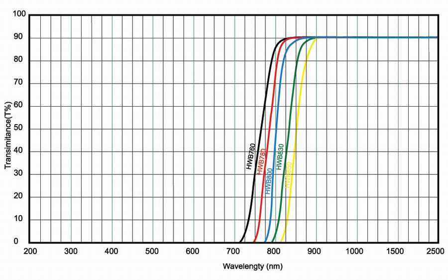
After understanding the use case, the guy was recommending to use "ZJB270" UV glass instead, as it is cheaper than sapphire glass and has a wider pass through spectrum:
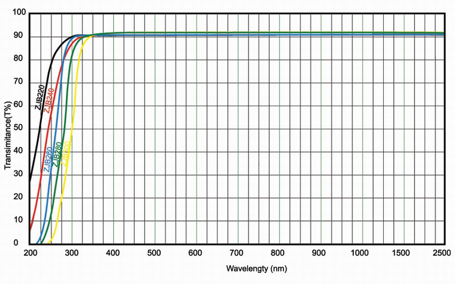
For an order of 6 circle shaped lenses of 25x1.5mm they want USD 5.00 each. I think I will pull the trigger on these. The very responsive guy is from "Nantong Foric Optical Glass Factory Store" (https://m.de.aliexpress.com/store/storeHome.htm?sellerAdminSeq=233076620&version=v2#/). If the glass does indeed work, I can highly recommend them.
I'll order some O-Rings for sealing to an enclosure.
Last but not least, I would like to print one of your enclosures for testing. There have been some new files with yesterday's date. There is a considerable amount of variations now. Which one shall I use?
Cheers and thanks,
TS
_________________
Torben Schreiter
|
Magnus Thomé
Stockholm
Här sen Nov 2002
Inlägg: 41618
Forumägare
Trådstartare
29 Sep 2019 12:31
Senast ändrad av Magnus Thomé, 30 Sep 2019 10:21, ändrad totalt 1 gång
Really really great news if these transparents work! Great find! Keep me posted
Regarding housings and holders I've just made a new variant where you can mount the temp sensor pointing out of the end of the housing instead:
"Main Housing (ALT. temp sensor mounting)"
This can sit just in front of the rear tire for example under the car. Temp sensor pointing backwards towards the tire and the distance sensor pointing down towards the ground. Short tube for wide angle temperature sensor, long tube for narrow angle sensor.
I'm also just making a protective snap-in box/holder for it that can be permanently attached to the car. Will upload that shortly.
The distance sensor must be connected with short wires instead of direct mounting on the main board. It is very tight so thin short cable should be used.
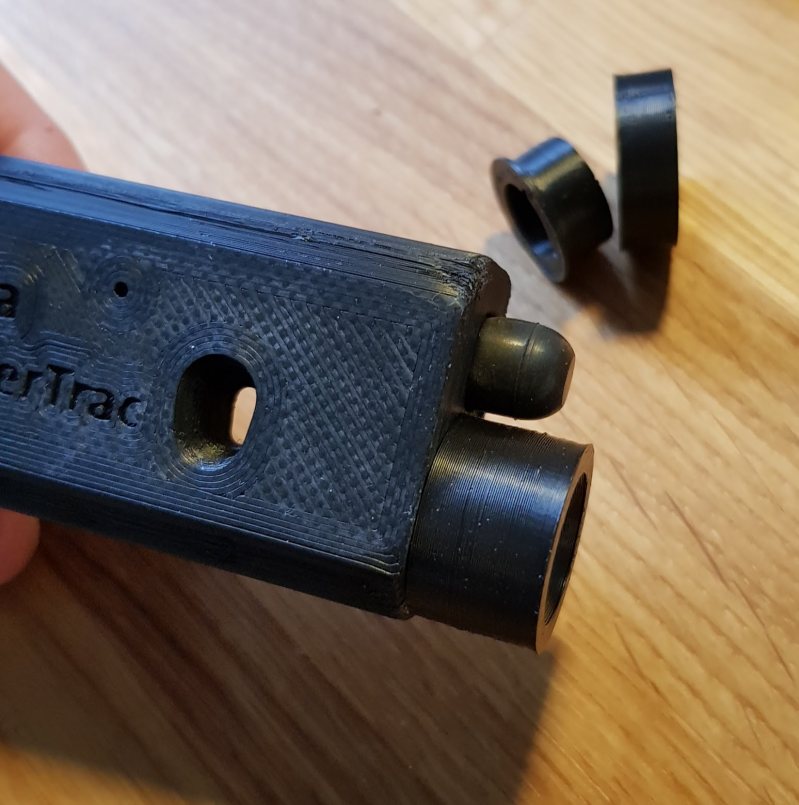
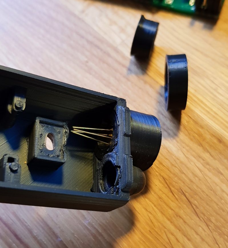
Then you have two almost identcial variants of the main housing. The only difference is how the protection window for the distance sensor is placed. One ("CONE for dist. sens.") has a deep cone as a hole down to the distance sensor where you mount the protection window squeezed between the sensor and the housing where the sensor is mounted as described earlier quite close to the main board.
The second variant ("ELEVATED dist. sensor") instead has two small holes as windows where the sensor is placed further up away from the main board (just use longer connection pins). Still squeezing the protection window between the sensor and housing but now much closer to the front side of the housing, further away from the main board. Which you choose of these two is a matter of taste :-)
You can always click on the STL files on github and get a 3D view of the model
https://github.com/MagnusThome/RejsaRubberTrac/tree/master/3Dprint/pri . . . .
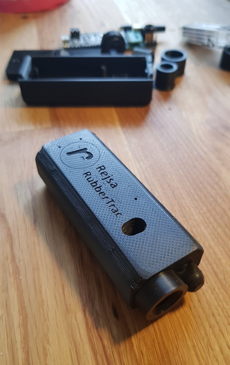
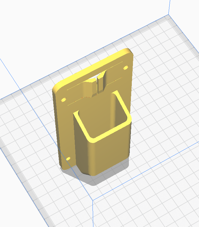
Here's the snap in holder to mount under the car for the "ALT. temp sensor mounting" housing
_________________ Magnus Thomé
|
Magnus Thomé
Stockholm
Här sen Nov 2002
Inlägg: 41618
Forumägare
Trådstartare
29 Sep 2019 12:41
_________________ Magnus Thomé
|
|


 A bunch of questions answered :-)


