| Allt Nytt | Kalender | Racerbanor | Arrangörer | Forum | Varvtider/Loggar |

 |
Racetech
 formula for cone manifold
|
17 besök idag (16647 totalt) |
|
formula for cone manifold
hi all I thought maybe here someone would have an idea on a formula/rule for the dimension of the converter cone on a Lehmann style manifold ? (manifolds with plenum and a conical primary chamber connected via a slot) 
I can eyeball dimensions from pix but was wondering if there would be a more clever way thx in advance ! 
_________________ Gerhard 81 Quattro 87 Scirocco 87 TX152 

|
||||||||||
|
Dahlbäck racing offers a similar inlet manifold (probably made by Lehmann), here's some pictures:


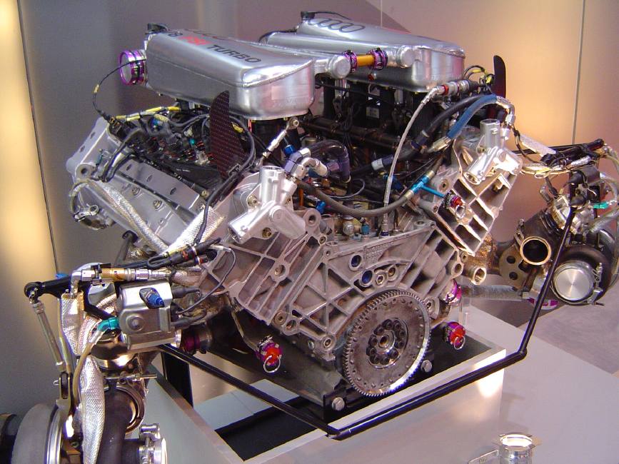
Inlet manifolds with similar style have been used in several Audi racing cars; including the 90 IMSA GTo and Audi R8. Below the R8 engine manifold: 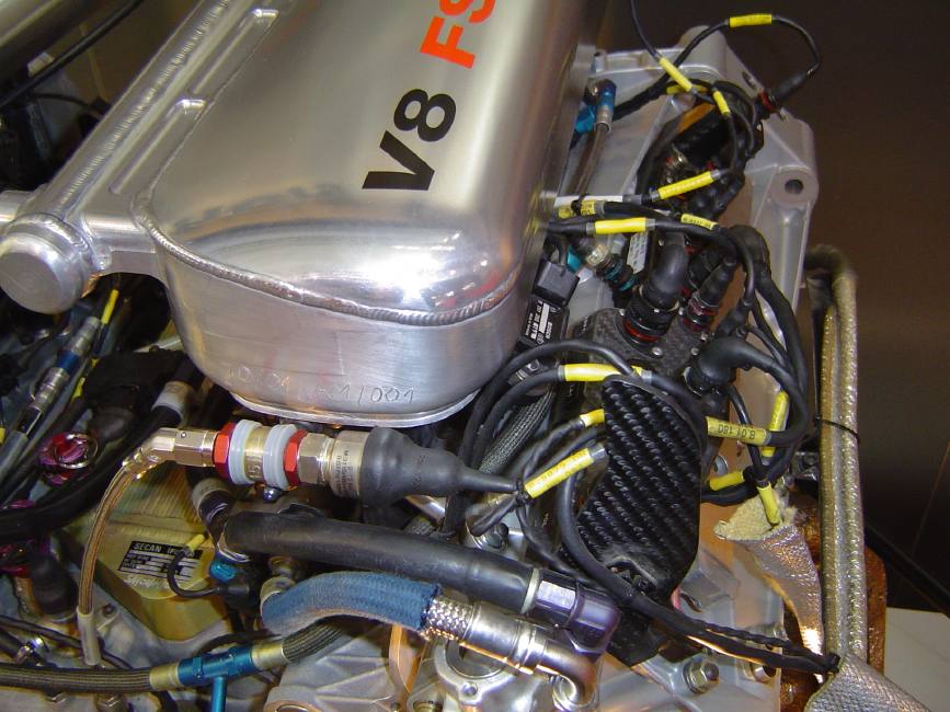
and the IMSA GTo manifold 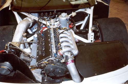
The reduction in area of the supply pipe is supposed to create an even pressure in the plenum chamber so that no cylinder gets more air than the other. I would guess that they reduce the diameter of the pipe so that the flow velocity in the supply pipe remains constant all the way. The area of the passage between the supply pipe and the plenum is probably similar to the large end of the supply pipe so that there are no sudden changes in air velocity. That should give the basic setup, then I would expect some tests have to be done were the airpressure in the plenum is checked at each inlet duct. The bellmouths should preferbly be made with an elliptical profile (explained here http://www.profblairandassociates.co
|
||||||||||
|
thanks for the answers guys
I don't know if the dahlback unit is made with Lehmann but it sure looks very close to the "skoda wrc" units afaik, Lehmann is the creator of this design my goal is not to build a perfect unit but to be the "less wrong" possible... not even sure I will use fish/bellmouths as budget is tight, however I will read this pdf in detail, looks very interesting but not sure I will understand everything ! 
honestly, the plan is to use exhaust bends for the runners. 
I was thinking already to make the slot the same area as the throttle body for the cone, I was thinking something roughly like this, maybe a bit steeper... 4 > 21.6 3 > 32.5 2 > 43.3 1 > 54.1 Intake > 65 some formulas I have for atmo plenum/runners, not sure they really apply here... Runner length : 17.8cm at 10,000 rpm makes a good starting point. (In this context, "runner length" refers to the distance from the inlet valve to the plenum chamber.) Add to this length 4.3cm for each 1000 rpm less that the system is being tuned for. Tuning for peak torque (not peak power) is the norm, and so if the engine were being tuned for 4000 rpm, a runner length of 43.6cm would be required. You can see that for an averagely-sized engine bay, the longer the runner that can be fitted in, the better! Runner diameter : multiply the engine volume in litres by the engine's volumetric efficiency, then by the tuned rpm, then divide this sum by 3330. The final figure is square rooted, giving the runner diameter in inches. As an example, a 5 litre engine with an 80 per cent efficiency (expressed as 0.8) and tuned for 3000 rpm, will have a runner diameter of 1.9 inches, or 48 mm. sqr((1800*0.8*4000)/3300)=41,77mm (it is correct to apply the same formula in metric ?) Plenum volume : should be around 80 per cent of the volume of the cylinders to which it is connected. (1800*80%=1440cc) thx for any advice dudes ! 
_________________ Gerhard 81 Quattro 87 Scirocco 87 TX152
|
||||||||||
|
Re:
If the intake is 65 mm, for a constant flow velocity the pipe diameter should be about 56 mm before the second cylinder, 46 mm before the third cylinder and 32.5 mm before the last cylinder. Then we have the areas 3318, 2463, 1662 and 829 mm^2.
Those numbers seems to be a bit off. I also can't se what physics they are based on one calculation method is given by Boretti and Secchi:
Lip = minimum length of inlet pipe ap = average speed of sound M = averaged mach number within the pipe during valve opening N = engine speed, rpm At ambient temperature the average speed of sound is about 330 m/s. The average mach number within the pipe during valve opening can be found using for example engine simulation software. For calculation of F1 inlet runner lengths Boretti used a value of Lip of 3.358*10^6/N, so a inlet pipe using those same values for 10000 rpm should suggest a length of 3.358*10^6/10000 = 335.8 mm. If the length in the head is say 80 mm, the inlets should have a length of 255.8 mm. At 8000 rpm we get a length of 420 mm, which I think is similar to what is used on super touring car engines.
Runner diameters are determined by the port sizes. This means that you must know how large your inlet ports are. The port area you should measure is the "small diameter" above the inlet valve. Say that you got a four valve engine where the ports measure 32 mm and the valve stem 5 mm. Then each port size is (Pi*32^2/4)-(Pi*5^2/4) = 785 mm^2 and since you got two ports the total area is 1570 mm^2. In the head the area is first reduced then increased. So where the inlet manifold meets the head the port area is usually 0.9 to 1.1 times the port area (the smallest area in the head can be below 0.8 times the port area). Say that we use a ratio of 0.95 with our 32 mm ports then the pipe of the inlet manifold should end with an area of 0.95*1570 = 1491.5 mm^2, that is a diameter of 43.6 mm. It's then common to increase the area in order to reduce the flow velocity in the intake runners. It's common to increase the size of the runner to about 2 times the size of the port area. This means that the pipe, before the bellmouth can have a area of 2*1570 = 3140 mm^2, that is a diameter of 63.2 mm.
To calculate a suitable size for the plenum we can use Helmholtz resonator and try to find a plenum size that has a resonant frequency equal to the engine at one particular rpm. It's of course also possible to use a more pratical approach by simply pick a size and test it. NA engines seems to like large plenums. I've run a few engine simulations with Lotus with various plenum sizes and it seems that the highest engine output comes with a very large plenum, often 6-7 times the engine displacement. But on a turbo engine such a large plenum would no be suitable due to lag, as the turbo will need to pressurize before the engine will give maximum torque.
|
||||||||||
|
thanks a lot for the answers, I will try to integrate all that and make the better compromises
I think the text wich I refered to came from this http://www.autospeed.com/cms/A_107771/article.html I have to admit this kind of physics are way outta reach for me so it is entirely possible I misinterpreted it or wrongly took sentences outta context ! thanks again for the help anyway, I will post details when I have the time to work it out. I just found a shop that will do the CNC laser cuts for the flanges ! 
for the fun some pix of a cardboard mockup I made first... 


_________________ Gerhard 81 Quattro 87 Scirocco 87 TX152
|
||||||||||
|
hell yeah !
I am also going to use a GTD exhaust !  (and an honda injection and a saab turbo ! (and an honda injection and a saab turbo !  ) )
this is a locash project...90S engines are worth a bag of peanuts in about any decent junkyard and I already have a spare one so if I grenade it, no problem. also going back to original would be a lot easier if needed...this is supposed to be a street legal car
another thing is that I like something original...what the point in making another t16 or tG60 ? vagheads forums are full of them (btw the G is a 8V reverse flow too and it yelds pretty good results...) I had to build the manifold anyway so at least let's make it sexy ! btw I see you have a 75T, I a am also working at a turbo for a Giulietta 1800 "turbodelta" style with the carbs...but also with a cone  should be fun. should be fun.
_________________ Gerhard 81 Quattro 87 Scirocco 87 TX152
|
||||||||||
|
hey guys
an update on the project...I know you couldn't sleep waiting for it. I've switched from Autocad to Turbocad and it's much better this is an other proof that a turbo is better than an auto. anyway. I try to obtain solidworks now. here are some calculations I came up with ! the runners will be hitech exhaust bends that are 39mm inner diameter runner lenghts...I decided I'll use the "it's a turbo mess anyway" rule
the stock ports are two 29mm half circles and a 5x29mm rectangle wich gives an area of 660 + 145 = 805 the 39mm runners are 1194 but they will have to be fluted a bit (yeah, more hazardous welding) inlet area = 60mm > 2826 (plenum outlet area 1194 * 4 = 4776) surface slot the slot is finally 310mm long so...the slot has to be beetween high figure, outlet : 4776 / 310 = 15.4mm and lo figure, inlet : 2826 /310 = 9.1mm please someone fix my calculations as there is most possibly an error in there so I guess it's gonna be 8/10 mm ? I was tempted to make it a tad on the small side to keep a higher pressure differential inside the cone as to "stuff air in a funnel" I have changed the plenum shape but I am not even sure yet that this will fit in the car so maybe it will not be possible as the hood is very low. I have no idea how to calculate its volume now. shape is far too complicated for my poor geometry ! as for runners bellmouth...I know it would be better but that's another order...another headache...and as someone says, this is already the best manifold concept on one of the worst head ever so maybe not worth it ? especially since, ahem, noone will see them so the bling factor is low. Yeah, bling ingineering crossed over with group B technology, so what ? 


_________________ Gerhard 81 Quattro 87 Scirocco 87 TX152
|
||||||||||
|
Re:
Regarding your mainfold, i think you are barking up the wrong tree... take a look at this project from the second page, Do studdy the "inside" of the plenum how he have made the "slitz" from the pre-mainfold into the main chamber. (i dont know if you have to regester to see this, but that you fix in a flash) http://www.mbsca.com/forum/viewtopic _________________ Johan Carlsson 
Mercedes-Benz 190E 2.5-16 -92 VW Golf mk2 GTi 8v 1985 GrpA
|
||||||||||
|
Senast ändrad av Bandido, 14 Mar 2007 21:33, ändrad totalt 1 gång
ok, I'm checking it out...
here are some of the last 3d sketches... no design change but added _ current Honda throttle body (complete with throttle plate and return spring ;-) and flange _ also figured the dashpot as I think I'm gonna use it _ Bosch injectors (no seats yet !) _ injectors heatshield/firewall _ flipped GTD exhaust manifold 


_________________ Gerhard 81 Quattro 87 Scirocco 87 TX152
|
||||||||||
|
as I said, I try to keep it simple...this is (supposed to be) a locash/fun project
the first "design" for it was a lenght of 70mm steel tubing and 4 exhaust elbows and cut flanges with hacksaw, holesaw, etc, in a pure old junkyard style then it all got somewhat out of control
_________________ Gerhard 81 Quattro 87 Scirocco 87 TX152
|
||||||||||
|
ok dudes, I know you are sick of horribly colored 3d pix but yet here are some more
I've added GT17, IC and tubing to my model... 
I managed to switch to Solidworks...it rocks !
here is the model imported but I am going to rebuild it in native SW. for some reason, the downpipe just disapeared during export/import 

here is what I did tonight...this comes from actual Garett datas except the interior has been "filled up" otherwise, it is an exact model of a GT15VNT. I imported the parts and assembled them into SW. Only one connection is "faked" (I dragged the part into position), the VNT rod connection to the lever could not be mated, it kept on saying there is a 0.000713° error in alignment. if you watch close, you can see it is not a perfect fit ! darn. I got the datas from a Formula SAE forum. FSAE is an american students formulas, cars are cross breed of a formula and a big kart, they are very fast and usually very hitech. 
_________________ Gerhard 81 Quattro 87 Scirocco 87 TX152
|
||||||||||
|
some pix found on the forum, I like !
(but it seems since, one even more beasty manifold was made) 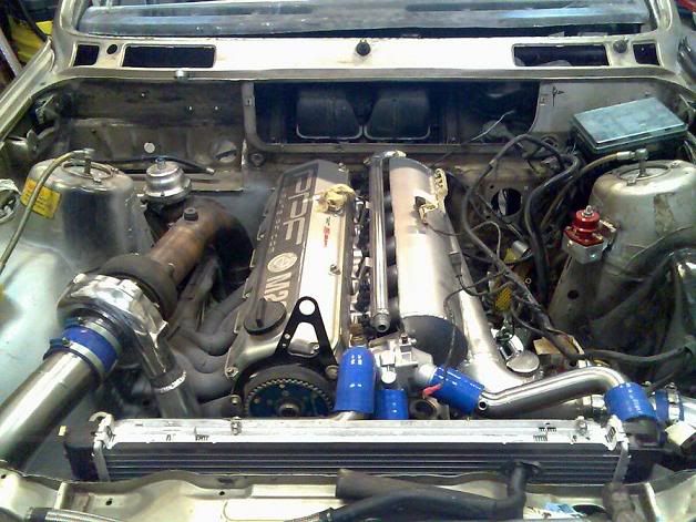
original post : https://rejsa.nu/forum/viewtopic.php?t=36142 _________________ Gerhard 81 Quattro 87 Scirocco 87 TX152
|
||||||||||
|
some more 3d progress...now all in native solidworks

so here is the new version...quite a change from the old autocad stuff ! 
the design of the fuel rail was "stolen" from Johan Carlsson's 190E 2.5-16 ! there is one "small" interference problem with fuel rail being very close to the TB. 
the holes on top of the plenum could be for water injection ? 
one nice detail...angle coupler beetween the cone and the TB flange, fuel rail/injector coupler ghost view, injector connector... 
Bosch injector...one of the first "about correct" model I made ! very proud... 
trying to build a shifter model... 
this is a closeup on a test part with patterns of dozens of holes in every directions...vasarely is my bitch
that's it you crazy vikingz hope you dig it
_________________ Gerhard 81 Quattro 87 Scirocco 87 TX152
|
||||||||||
|
Racetech
formula for cone manifold
|
17 besök idag (16647 totalt) |